SDI-5283 Ultrasonic Heavy Duty Bar/Cylinder Inspection System
![]()
- System Overview
- Mechanical Configuration
- Instrumentation / Motion Control
- Acquisition/Analysis
- Installation/Training
SDI-5283 SYSTEM OVERVIEW
 This specification is for a rugged single or multi channel, high-resolution ultrasonic test system for heavy bar or cylinder inspection. The SDI-5285 rotator system with irrigated transducer test head can be installed at floor level in harsh industrial environments.
The ultrasonic instrumentation and motion components are stored in a heavy duty housing for protection against dropped tubes etc during loading. It is designed to achieve the accuracy and resolution required at high throughput speeds in a harsh operating environment.
The system will test product with diameters ranging from 6 in (150mm) to 24 in (600 mm). The standard system can be configured for lengths up to 20ft.
 SDI have supplied systems of this type for testing product with diameters ranging from 2 in (75mm) to 16 in (355 mm). with lengths up to 35ft. (8m)
Note: This specification is for the standard SDI-5270 Bar Inspection System and is for information only. The details may differ significantly from those proposed for specific customer requirements.
The specification provided in the Statement of Compliance and formal quotation supersede this document.
MECHANICAL CONFIGURATION
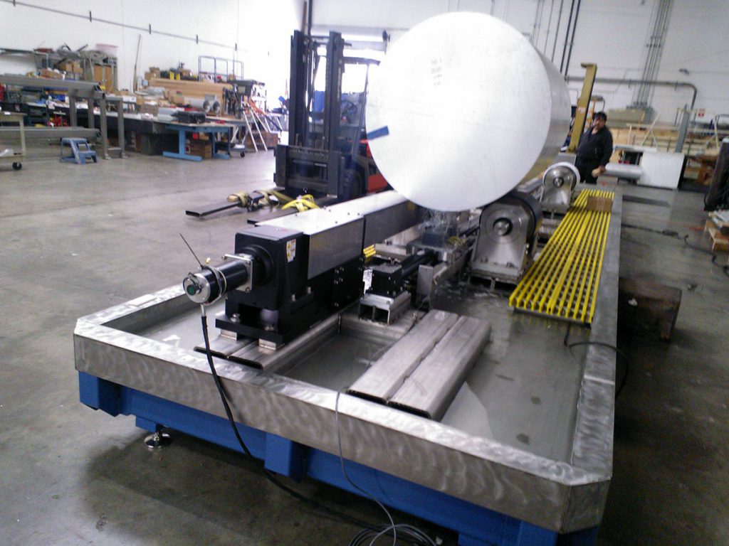
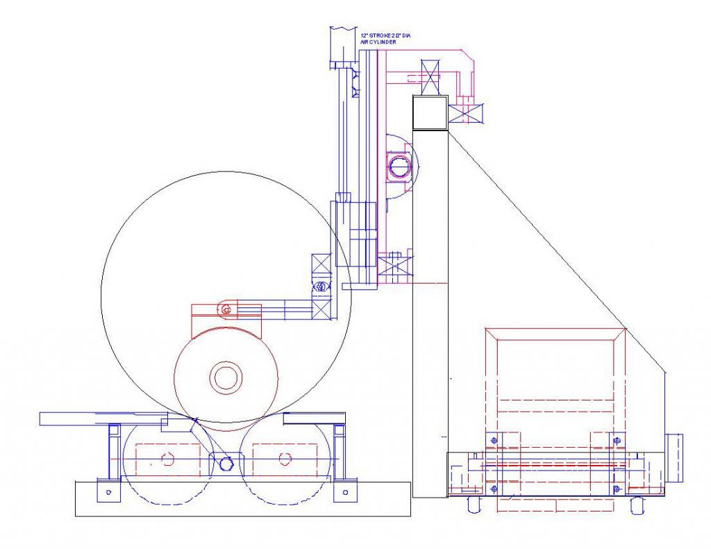
The system consists of floor mounted sump supporting a 20ft (8m) long SDI-1334 heavy duty rotator. The transducer(s) are mounted in-line in a high flow irrigated housing which rides in contact with the bar.
This type of housing is used extensively on the SDI compressed gas cylinder inspection systems which are used with very heavy duty cycles on a variety of rough surfaces. It provides coupling equivalent to an immersion system as a water filled chamber is maintained between the transducer and the part.
The test head is mounted on a cantilever bridge equipped with a bar follower assembly. There are a number of different contoured shoes which can be rapidly changed by the operator to accommodate different bar diameters. Each shoe size will test several different bar diameters.
The bar to be tested is loaded onto the rollers while the transducer/follower assembly is parked in a housing at either end of the scanner. As the bar is rotated, the transducer assembly traverses the entire length of the bar.
All test parameters, including rotator speed, helix pitch etc are controlled by the SDI-1830-UTB system controller. The time to test a bar is dependent on the test standard defect size and determined by the bar diameter. To reduce inspection time the testing is performed bi-directionally.
The test bridge moves off the bar into a shielded housing at the end of each scan. It remains protected until the next bar is loaded onto the rotator then it emerges and travels the opposite direction down the length of the next bar and into housing the other end. The sequence is repeated for each bar.
The modular design allows rapid reconfiguration of the system to accommodate different lengths and diameters of bar. The detailed description of the modules is given below.
TEST STATION
The test station is the main operating station of the system and contains the sump, rotator, bridge and system controls. In the majority of systems, the instrumentation and system controls are housed at the end of the test station, as this is where the operator will usually be located.
The test station frame is fabricated from welded steel and finished with epoxy paint. The overall length is 30ft. and the depth 3ft. The SDI-1334 rotator will function in either direction with continuously variable speed. The maximum speed is 40 surface in per sec.
AUXILIARY MODULES
A number of auxiliary modules are available for improving the inspection efficiency.
DEFECT MARKERS
Automatic defect markers are available for indelibly marking the product downstream of the test station. Both paint jet and felt tip markers are available.
DEFECT LOGGING
A computer-based defect logging package is available for producing a tabular output of defect location and material length.
WATER CONDITIONING UNIT
A recirculation pump and filter system ensures water quality is maintained under normal working conditions. Optional temperature control and de-airation units can be provided.
INSTRUMENTATION
The instrumentation used will be the SDI-2480 multi-channel flaw detector available with up to 8 channels. This high speed, high-resolution instrument is designed for industrial on-line applications where features such as the interface gate synchronization eliminate variations due to surface conditions and bar flutter.
The unit has up to eight sequenced channels each consisting of a pulser/receiver module. Each channel will accommodate four gate modules with rear panel outputs and front panel LED displays indicating the gate condition.
For each channel a flaw gate LED will be illuminated if an echo appears in the gate above the pre-set thresholds. Thickness modules are available if required.
SYSTEM CONTROL
All system functions will be controlled and monitored by the SDI-1830-UTB system control module. This is an integrated suite of software modules running on a rack mount industrial P.C. with an optional touch screen display.
There are four main functions: – 1) Instrument set-up and display, 2) System control, 3) Operator input, and 4) Data logging. The screens can be custom designed for particular applications. Typical screens for each of these functions are shown below. These could be reconfigured as required.
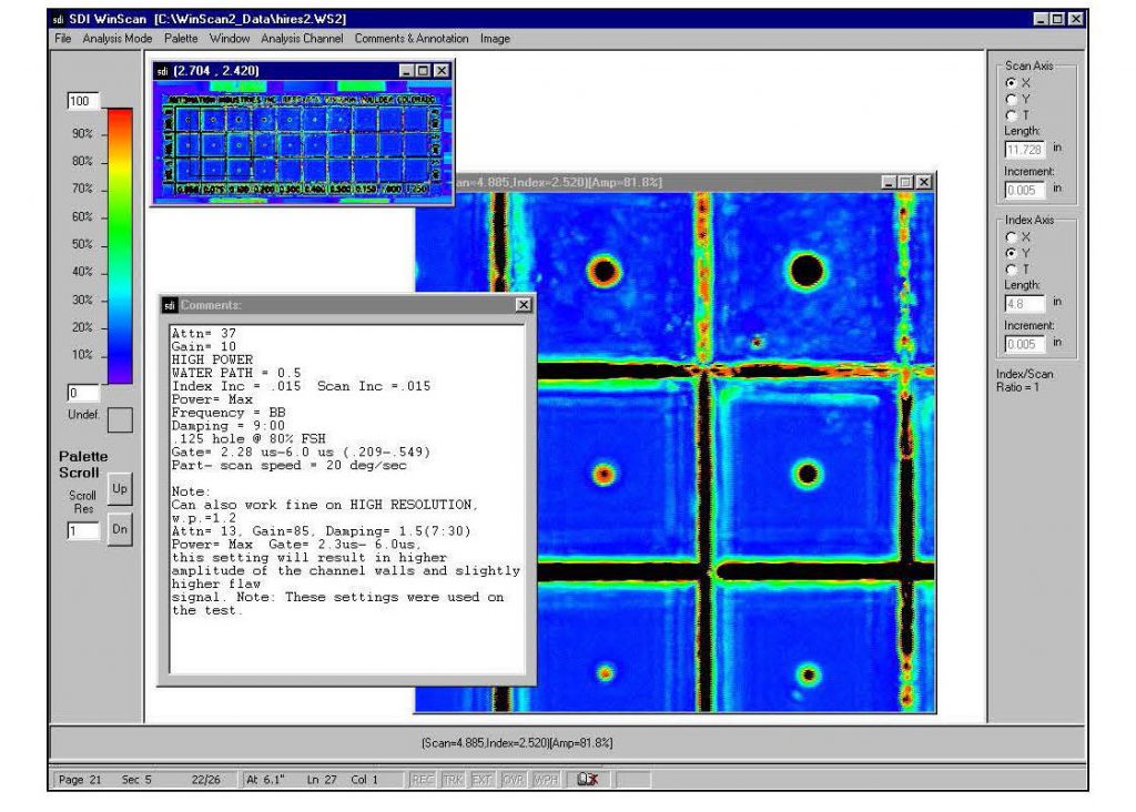
This screen allows each instrument channel to be set up and directs the video and gate outputs from the selected channel to the display scope. At any time the operator can view the A-scan display of any channel by touching that channel number on the screen. All set-ups can be stored and recalled with a file name. Other functions controlled include:
This is the main screen for controlling system configuration parameters and defect location markers when supplied. The inspection helix pitch is controlled as determined by the required defect detection level. The system controller controls the drive speed and helix angle of the system. For more automated systems this module receives input from various sensors on the system and instrumentation and determines a sequence of events based on these inputs. The precise sensor input is determined by the type of test being performed and the options installed. Custom inputs can be accommodated for special functions.
For the variable input levels, both digital and analog, internal comparator logic allows the operator to set high and low thresholds for the quantity being measured. When these thresholds are exceeded the required response can be programmed. An example of this device would be the marking of regions where different types of defect occur.
Other parameters monitored are rotational speed and linear velocity of the bridge. Part diameter can be entered manually or automatically measured.
There are a wide range of programmable controller responses, examples of these are 1) delayed response, for the action of down stream devices, such as paint markers or sorting stations, and 2) defect indication suppression. This is required at or near the end of a bar. It also provides direct operator jog control allowing the system to be reversed to investigate defect indications.
SYSTEM CONTROL
The system is supplied with the latest SDI-WinScan multi-tasking acquisition and analysis package designed for high throughput production applications. A technical description of the features and benefits of this high performance industrial package is attached. Some of the key features are:
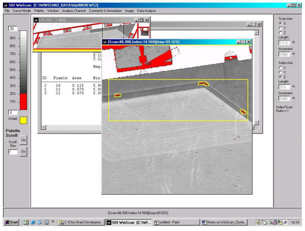
Another time saving feature of the fully integrated motion control and data acquisition package is the ability to perform mini-scans. Areas of interest can be tagged on the data file and the system will automatically drive back to them and re-scan the area using selected defect evaluation scan parameters such as full waveform capture.
INSTALLATION
The system will be fully assembled and made operational at the SDI facility in Camarillo for customer buy off. The Acceptance Test Procedure (ATP) will be carried out using the test samples supplied by the customer. SDI will address any items requiring rectification prior to authorization for shipment by the customer representative. Upon receiving approval, SDI will dismantle, crate and ship the system. SDI will carry out site preparation prior to the arrival of the system. The system will then be assembled and made operational on site. The ATP will then be repeated. The system timeline is attached.
TRAINING
SDI provide a comprehensive training program including 5 days training of personnel in the operation and routine maintenance of this equipment. This training will take place either at the SDI facility or at the customer site after installation.
![]()