Ultrasonic Bubbler Systems
SDI manufactures a range of bubbler or irrigated transducer systems. This type of system is usually product specific where full immersion is not possible and the laminar flow squirters with coupling distances of over 6 inches are not necessary. These relatively low flow volume systems systems including those designed to test compressed gas cylinders, automotive components, and metalic stripand the SDI range of portable scanners.
SDI-5280 AUTOMATED ULTRASONIC HEAVY DUTY CYLINDER INSPECTION SYSTEM
This specification is for an automatic, multi-channel, high-resolution ultrasonic test system for heavy tube or bar inspection. The SDI-5280 rotator system with irrigated transducer test head can be installed in-line with automatic load and unload stations. Sorting chutes and paint markers are also available. The ultrasonic instrumentation is a bridge-mounted multi-channel OEM-SOCO-8S-UT Ultrasonic Flaw Detector. It is designed to achieve the accuracy and resolution required at high throughput speeds in a harsh operating environment. The system will test product with diameters ranging from 3 in (75 mm) to 8 in (325 mm). The standard system can accommodate bar lengths up to 15ft. Options are available for longer length bars.

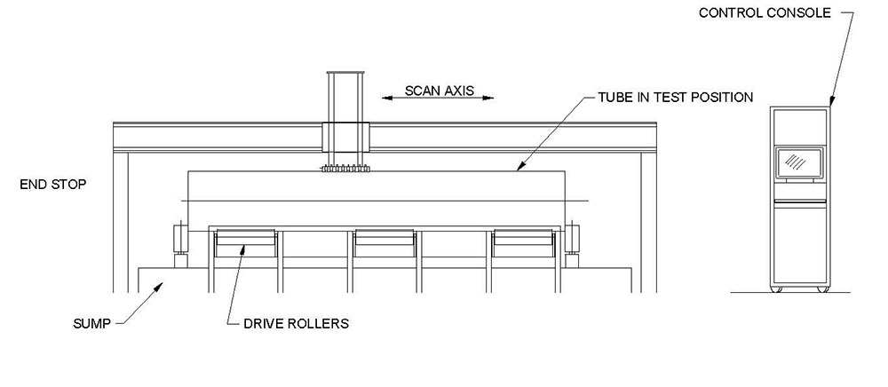
SDI-5280 Overview

The system consists of floor mounted sump supporting aN SDI-1332 medium duty rotator. The transducers are mounted in-line in a high flow irrigated housing which rides in contact with the bar.
This type of housing is used extensively on the SDI compressed gas cylinder inspection systems which are used with very heavy duty cycles on a variety of rough surfaces. It provides coupling equivalent to an immersion system as a water filled chamber is maintained between the transducer and the part.
The test head is mounted on a bridge equipped with a bar follower assembly. A second test head can be added to cut scan times in half. There are a number of different contoured shoes which can be rapidly changed by the operator to accommodate different bar diameters. Each shoe size will test several different bar diameters.
The bar to be tested is automatically loaded onto the rollers and the transducer/follower assembly lowered onto it. As the bar is rotated, the transducer assembly traverses the entire length of the bar. All test parameters, including rotator speed, helix pitch etc are controlled by the SDI-1830-UTB system controller.
The time to test a bar is dependent on the test standard defect size and determined by the bar diameter. To reduce inspection time the testing is performed bi-directionally. The test bridge moves off the bar into a shielded housing at the end of each scan.
It remains protected until the next bar is loaded onto the rotator then it emerges and travels the opposite direction down the length of the next bar and into housing the other end. The sequence is repeated for each bar. The principal components are:
The modular design allows rapid reconfiguration of the system to accommodate different lengths and diameters of bar. The detailed description of the modules is given below.
Test Station
The test station is the main operating station of the system and contains the sump, rotator, bridge and system controls. In the majority of systems, the instrumentation and system controls are housed at the end of the test station, as this is where the operator will usually be located. The test station frame is fabricated from welded steel and finished with epoxy paint.
The overall length depends on the length of bar to be inspected. and the depth is 3ft. The transport roller centerline height is 39in. The SDI-1332 rotator will function in either direction with continuously variable speed. The maximum speed is 40 surface inches per sec.
Material Transport Modules
The material transport modules are two different modules for handling the material as it progresses through the test system: Loading Station and Off Loader Station. All transport modules are manufactured from heavy duty welded and bolted steel construction. Adjustable leveling feet are used on each station to allow precise alignment.
The rollers used are manufactured from high-density polyurethane or neoprene as determined by the application. The frames are finished with epoxy paint.
LOADING STATION
Product is loaded onto a feed ramp, which can be built to any length to allow for accumulation of product. A pneumatically operated part selector separates a single bar and positions it on the rotator rollers. The bar then rotates and the test head moves at a speed determined by the required helix index.
OFF LOADER STATION
Air actuated off-loaders are provided with various numbers of lifting arms to suit different length bars. Defective parts can be directed to a reject stack. Automatic defect marking is provided.
AUXILIARY MODULES
A number of auxiliary modules are provided for improving the inspection efficiency.
DEFECT MARKERS
Automatic defect markers are available for indelibly marking the product downstream of the test station. Both paint jet and felt tip markers are available.
DEFECT LOGGING
A computer-based defect logging package is available for producing a tabular output of defect location and material length.
WATER CONDITIONING UNIT
A re-circulation pump and filter system ensures water quality is maintained under normal working conditions. Optional temperature control and de-airation units can be provided.

SYSTEM CONTROL
All system functions will be controlled and monitored by the SDI-1830-UTB system control module. This is an integrated suite of software modules running on a rack mount industrial P.C. with an optional touch screen display. There are four main functions:-1)Instrument set-up and display, 2) System control, 3) Operator input, and 4) Data logging. The screens can be custom designed for particular applications. Typical screens for each of these functions are shown below. These could be reconfigured as required.
INSTRUMENT SET-UP
This screen allows each instrument channel to be set up and directs the video and gate outputs from the selected channel to the display scope. At any time the operator can view the A-scan display of any channel by touching that channel number on the screen. All set-ups can be stored and recalled with a file name. Other functions controlled include:
Instrument set-up; gain, gate position and gate threshold.
Instrument response monitoring -either the alarm condition, the signal amplitude or the time of flight.
Multi-channel sequencing to prevent cross talk by sequencing pulsing, gate position and gate width on each pulse.
Transducer manipulation where motorized transducer positioners are used the positions of each transducer for each material, type and size can be stored as part of the test parameter set-up. (option)
SYSTEM CONTROL
This is the main screen for controlling system configuration parameters and defect location markers. The inspection helix pitch is controlled as determined by the required defect detection level. The system controller controls the drive speed and helix angle of the system together with the sequenced actions of the load station, off load station and sorter. This module receives input from various sensors on the system and instrumentation and determines a sequence of events based on these inputs. The precise sensor input is determined by the type of test being performed and the options installed. Custom inputs can be accommodated for special functions.
For the variable input levels, both digital and analog, internal comparator logic allows the operator to set high and low thresholds for the quantity being measured. When these thresholds are exceeded the required response can be programmed. An example of this device would be the marking of regions where different types of defect occur.
Other parameters monitored are rotational speed and linear velocity of the bridge. Part diameter can be entered manually or automatically measured.
There are a wide range of programmable controller responses, examples of these are 1) delayed response, for the action of down stream devices, such as paint markers or sorting stations, and 2) defect indication suppression. This is required at or near the end of a part.
It also provides direct operator jog control allowing the system to be reversed to investigate defect indications.
OPERATOR INPUT
This screen allows the operator to input the details of the product being tested.
DATA LOGGING AND DISPLAY
This screen shows the condition of the system alarms. All alarm outputs will be continually monitored using this SDI-1910 Posilog PC data logging package. When an alarm condition occurs the Posilog will record the channel number, alarm type and encoder counter reading. These values will be displayed on the screen and stored to disk. In addition, an optional paint marker will indicate the occurrence of a defect on the side of the bar. The defect log files will be accessible in read only mode from any other PC networked with the host.