SDI-5380 Delta X Gantry Through Transmission 3D Scanning Ultrasonic System
![]()
- System Overview
- Mechanical Configuration
- Electrical Configuration
- Instrumentation / Motion Control
- Acquisition/Analysis
- Installation/Training
SDI-5380 SYSTEM OVERVIEW
The SDI-5380 is a high performance, 3D curve scanning, UT system designed for both
through transmission and pulse echo testing of composites and bonded structures. The Delta
X Drive Bridge allows complex curve following in all orientations. A wide range of parts
positioning devices can be integrated into the programmable motion sequence. These
include horizontal rotators, turntables and head and tail stocks.
The system is designed to inspect a complete range of part geometries, such as aircraft control
surfaces, wings, doors etc in addition to highly contoured fuselage and cabin components.
The motion control, data acquisition and instrumentation components can be installed in a
system control room, or operated from a shop floor console. The system is based on modules
widely used in SDI’s product range, which can be viewed on our web site at www.sdindt.com.
All components/modules used in the system are designed and manufactured in-house by SDI
in their Camarillo, CA facility.
- System Feature
- Scan speed up to 35 ips.
- Linear Amplifier UT for greater defect amplitude resolution.
- Log Amplifier UT for greater dynamic range.
- Optional simultaneous dual channel through-transmission (TTU) and pulse-echo
(PE) providing four data files from one scan; one PE from each side and two TT at
different gain levels. - Four pulser selections – high power spike (1000v), high resolution spike(400v), tone
burst and square wave. - Optional coordinated parameter control – instrument parameters such as gain and
gate position can be built into a scan plan as additional coordinated “axes” changing
at rep rate speeds. - 130 dB dynamic range.
- 40dB Distance Amplitude Correction.
- Multi-processing allowing scans to be analyzed while they are being acquired.
- Auto-normalization and auto-teach of scan profiles.
- Complex curve following in any orientation, with 3 point part location.
- Optional full waveform capture usually used with mini-scan described below.
- Return to defect – automatic return to ROI identified by the operator.
- Mini-scan – automatic re-scan around ROI for defect analysis.
- Absolute encoding eliminating the need for frequent homing even after activation
of collision switch or E-stop. - 3D to 2D image mapping for accurate flaw sizing.
- Optional automated pen marking controlled from image analysis station.
MECHANICAL CONFIGURATION
All gantry members are welded box section. The gantry is mounted directly to the floor with a recessed or above floor sump fitted with water containment and recirculation components. The main bridge assembly is fabricated from welded aluminum tube forming an extremely rigid and stable box girder platform. Two Y axis carriages are mounted on ball shafts, each of which incorporates a Delta-X axis supporting the main Z drive assembly.
The Z axis search tubes are designed to accept a range of interchangeable gimbal assemblies for various applications. The standard extended reach gimbal/gimbal unit is used for the majority of applications where access is not a problem. Where there are restrictions, such as at the leading edge, the compact gimbal/swivel unit is used.
Linear Drives. The X axis motion is provided by driving the bridge assembly along steel rectangular section girders fitted with leveled aluminum tracks and ball shafts. Heavy duty dual power belt drive provides accurate positioning with encoder feedback. The heavy frame structure is designed to maintain positional accuracy throughout the operating range. The linear ways for Z, Y and delta-X axes are precision stainless steel, heavy duty, ball shafts with high endurance large diameter toroidal bearings. These are also fitted with precision rack and pinion drives or lead screws. All drives are closed loop d.c. with encoders/resolvers.
Gimbal Drives. The gimbals incorporate dc drives with resolvers and zero backlash harmonic drive gearboxes. The units are housed in sealed stainless steel enclosures as used on the SDI immersion systems.
Control Console. The mobile control console can be positioned anywhere within reasonable distance from the system. Current SDI systems have similar remote consoles up to 80 ft. from the scanner. It is fitted with two 21 inch monitors linked in the Windows operating environment to allow windows to be dragged from one screen to the next, or expanded over two screens. The console requires a single 110V 60 Amp single phase supply. SDI will install the necessary transformers to achieve this from the customer’s supply. The console houses all the computing, drive and instrumentation components required to operate the system. The enclosure includes a filtration and refrigeration unit.
Remote Operation. – A range of control functions, including teaching the part shape, can be carried out through a remote wireless pendant,(Windows tablet). Display of the TTU signal amplitude allows normalization of the transducer while standing next to the part rather than at the control console.
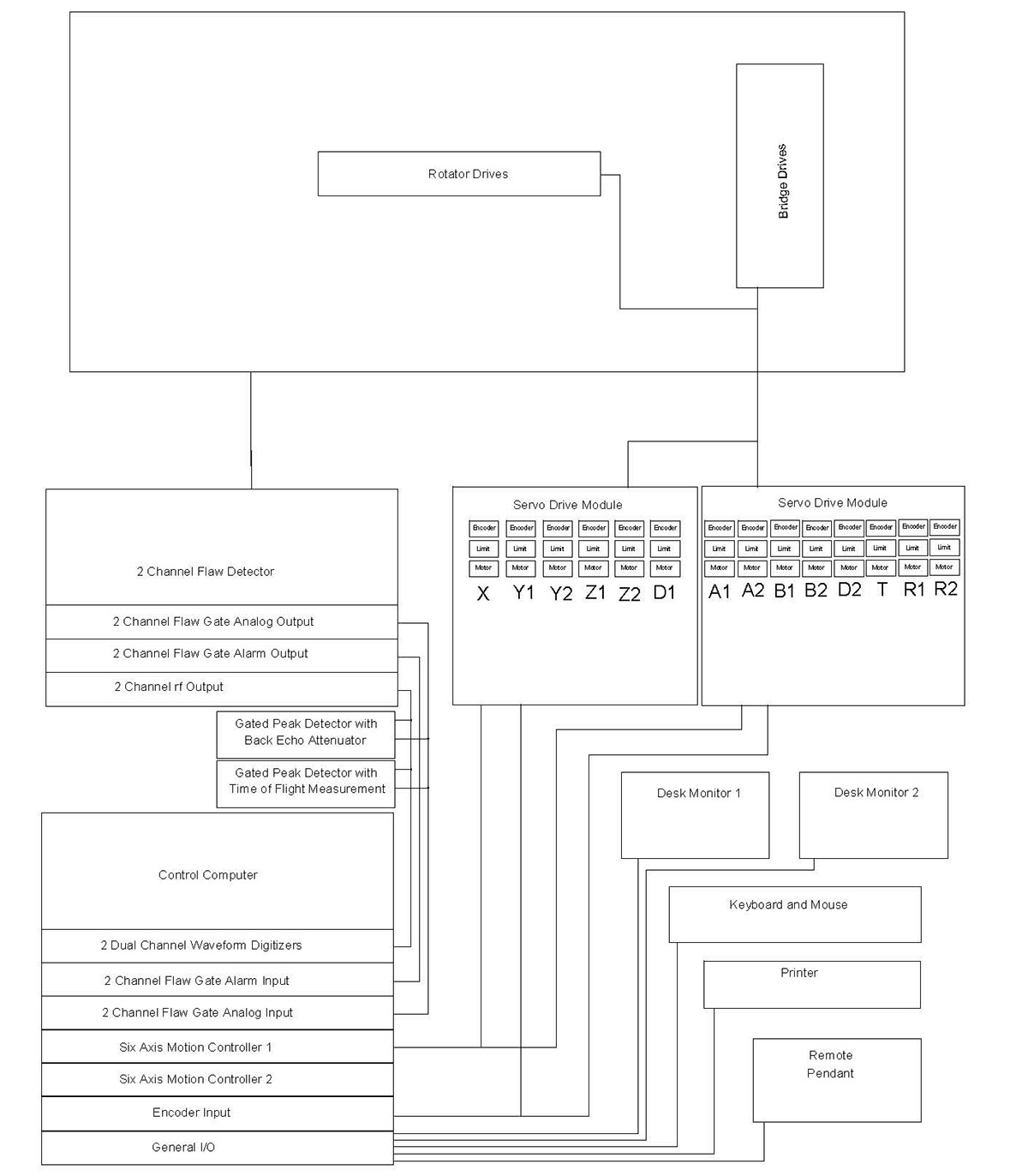
ELECTRICAL CONFIGURATION
The electrical configuration describes the components and interconnections for the motion control, drive, instrumentation and data acquisition sub systems. The majority of the components are housed in the system console. All system components meet applicable US and International safety codes.
Apart from the very low current ultrasonic signals, no voltages greater than 70 volts are present anywhere on the system outside the control console. The electrical layout is shown below:
INSTRUMENTATION
The system can be supplied with any two channel systems instrument from a major instrument manufacturer. The units can be configured to be able to provide simultaneous pulse echo from each side together with two through transmission tests, resulting in the acquisition of four channels of data in a single scan. A range of auxiliary instrumentation can be provided to aid in the inspection of the more complex highly attenuative lay-ups. This will include log amplifiers, pre-amplifiers, tone burst pulsers and air transmission modules. With the SDI dual frequency transducers, scans can be performed at two frequencies simultaneously.
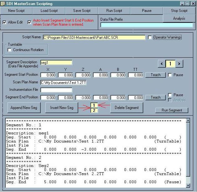
MOTION CONTROL
The motion control is provided by the SDI-1830 MasterScan advanced controller. Designed specifically for ultrasonic applications, it features ultrasonic functional axes and scripted scan plans. This means that complex motion control and acquisition activities unique to ultrasonic inspection techniques are available to the operator through simple commands using ultrasonic terminology. The operator can construct complex scans by chaining together individual motion commands, scan plans and instrument set-ups. Full details of MasterScan are given in the data sheet. Some of the key features are:
- Functional axes using standard UT terminology
- Import/Export of scan plans to CAD programs
- Automated normalization
- Auto teach of scan plans
- Integrated instrument control coordinated with the motion along a
- scan trajectory
- Scripted scan plans
- Chained scans
- Dual independent search tubes performing different scans
- simultaneously
- Stop on defect
- Return to defect
- Display of scan progress and time to finish
- Variable turntable rotation to maintain constant surface speed with changing diameter
- Taught slave positions for TTU
- RadScan – pre-programmed radius scanning.
- 3D display of taught shape.
ACQUISITION / ANALYSIS
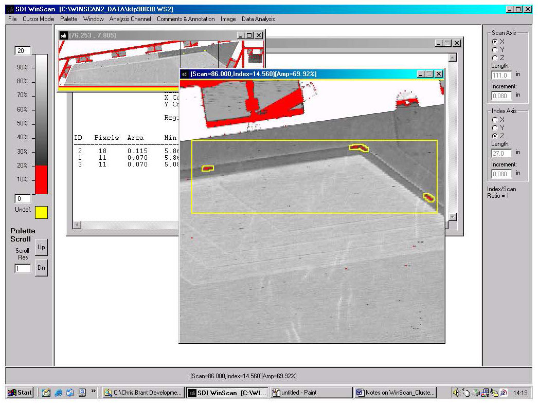
The system is supplied with the latest SDI-WinScan multi-tasking acquisition and analysis package designed for high throughput production applications. A technical description of the features and benefits of this high performance industrial package is attached. Some of the key features are:
Another time saving feature of the fully integrated motion control and data acquisition package is the ability to perform mini-scans. Areas of interest can be tagged on the data file and the system will automatically drive back to them and re-scan the area using selected defect evaluation scan parameters such as full waveform capture. 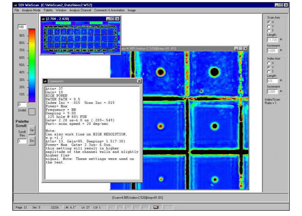
INSTALLATION
The system will be fully assembled and made operational at the SDI facility in Camarillo for customer buy off. The Acceptance Test Procedure (ATP) will be carried out using the test samples supplied by the customer. SDI will address any items requiring rectification prior to authorization for shipment by the customer representative. Upon receiving approval, SDI will dismantle, crate and ship the system. SDI will carry out site preparation prior to the arrival of the system. The system will then be assembled and made operational on site. The ATP will then be repeated.
TRAINING
SDI provide a comprehensive training program including 5 days training of personnel in the operation and routine maintenance of this equipment. This training will take place either at the SDI facility or at the customer site after installation.
![]()