SDI-5620 Horizontal Through Transmission Inspection System
![]()
- System Overview
- Mechanical Configuration
- Electrical Configuration
- Instrumentation / Motion Control
- Acquisition/Analysis
- Installation/Training
SDI-5620 SYSTEM OVERVIEW
 This specification details the SDI-5620 through transmission system suitable for a variety of high performance C-scan applications. The system is designed for the production inspection of advanced composite and metal bonded components.
The system employs modules used throughout SDI’s product range. It incorporates the MasterScan motion control and WinScan data acquisition packages, which are among the most powerful in the industry, together with SDI’s ultra low noise servo drive components.
All modules used in the system are designed and manufactured in-house by SDI in their facility in Camarillo, CA.
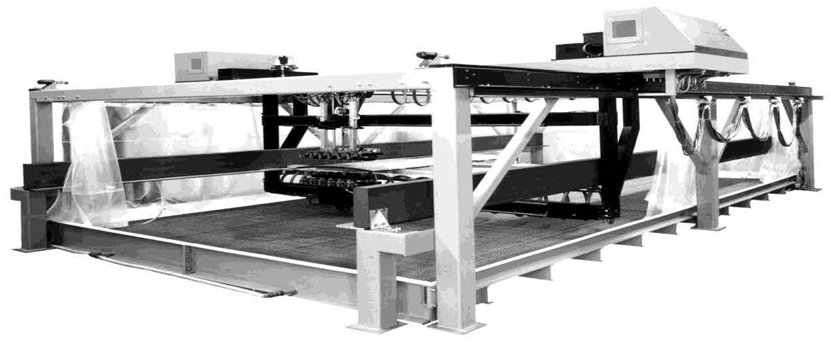
The design features a rigid aluminum heavy box section bridge, supported by a stand alone gantry. The bridge carries the upper Y axis 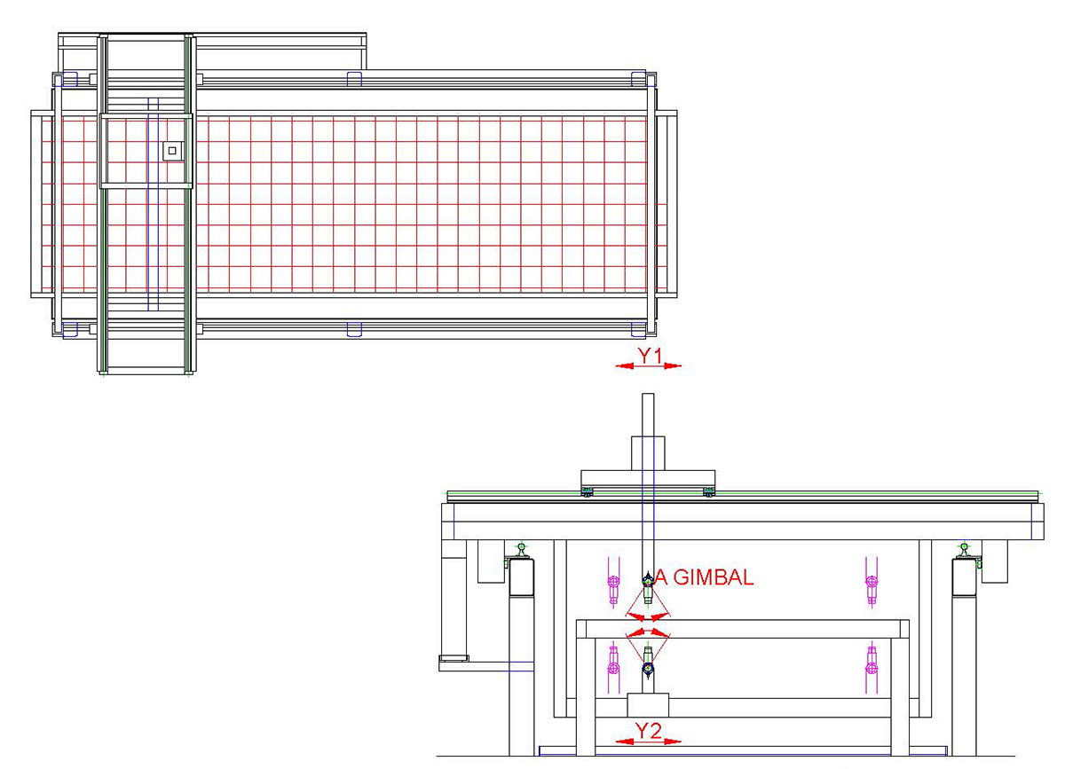 carriage with a motorized Z axis and transducer squirter assembly.
Supported beneath this is a slave Y axis carriage with a corresponding squirter and gimbal assembly. Drive components are housed in a stand alone control console, together with the motion control and acquisition computers.
Apart from the extremely low current ultrasonic signals, only low voltage drive voltages are present on the bridge and gantry making the system design extremely safe.
The axes of motion provided on the system are shown in the table below:
| Axis | Description | Range | Speed | Resolution | Accuracy |
|---|---|---|---|---|---|
| X | Primary axis along the gantry. High power d.c. servo drives with resolver. | 10-40 ft. | 24 in/sec | .001 in. | .004in/ft+/- 0.010in overall |
| Z | Vertical column rack and pinion drives. Manual with d.c. servo drives optional. | 1-1.5ft. | 2 in/sec | .001 in. | .004in/ft+/- 0.010in overall |
| Y1, Y2 | Rack and pinion drive d.c. motors and resolvers. | 8-12 ft. | 8 in/sec | .001 in. | .004in/ft+/- 0.010in overall |
The SDI acquisition software uses data swathing to combine the data from multiple transducers into a single file. The system can be made to automatically perform a defect evaluation miniscan, with full waveform capture, for every indication meeting the defect criteria used in the automatic cluster analysis.
MECHANICAL CONFIGURATION
The major mechanical components of the SDI-5640 are the gantry, upper bridge, lower bridge, squirter housing and vertical drive assembly. The squirter housing is fitted with a manually adjustable gimbal for transducer alignment. The system is also equipped with a stand alone sump.
GANTRY-X AXIS
The gantry is fabricated from heavy steel box section with a high redundancy outrigger design calculated to provide the required rigidity and stability for the large accelerating mass of the bridge and squirter assemblies.
The gantry is fitted with ground tracks with leveling jack screws and guide bars. Mounted to the tracks are the linear ways and heavy duty rack and pinion drive components to provide precise positioning and encoder feedback.
The gantry also carries the cable distribution components. All drives are closed loop d.c. servos with encoders/resolvers.
BRIDGE Y AXIS
The bridge is fabricated from heavy aluminum box section with a rigid box girder construction. Mounted to it are the precision V ways for the Y-axis carriages which support the Z-axis vertical drive housings. The design incorporates methods of adjusting the orthogonality and alignment of the X, Y and Z axes.
GIMBALS
The manual gimbals provide 10 degrees of adjustment in both the A and B axes. There is also lateral adjustment provided for precise alignment. The transducers are attached to the gimbals by a UHF mount.
PARTS POSITIONERS
Parts are supported in the system by a horizontal wire grid. The small diameter wires used are tensioned and will support components with loads up to 200 lbs. For heavier components, custom supports can be manufactured.
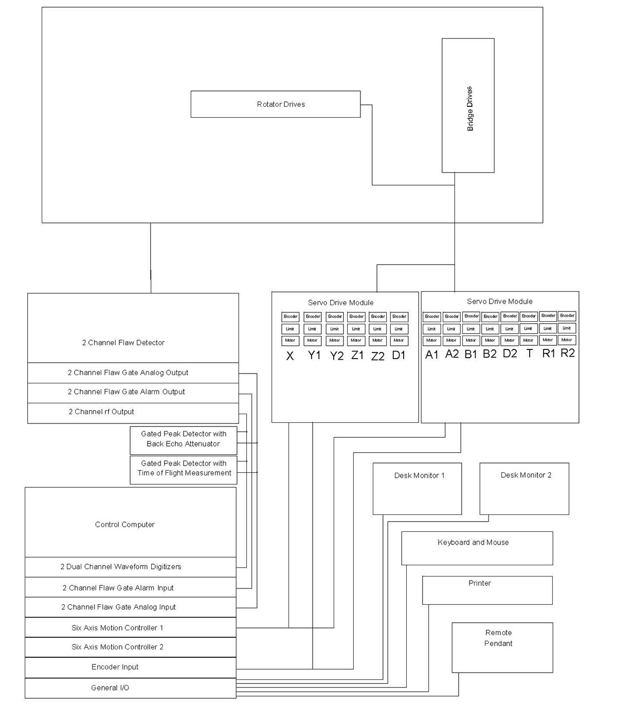
ELECTRICAL CONFIGURATION
The electrical configuration describes the components and interconnections for the motion control, drive, instrumentation and data acquisition sub systems. The majority of the components are housed in the system console. All system components meet applicable US and International safety codes.
Apart from the very low current ultrasonic signals, no voltages greater than 70 volts are present anywhere on the system outside the control console. The electrical layout is shown below:
INSTRUMENTATION
All SDI systems are able to operate with a variety of flaw detectors. Systems have been installed using instruments supplied by all major instrument manufacturers.
In addition, SDI manufactures their own range of high performance flaw detectors designed specifically for systems applications. When the SDI instruments are used there are a number of system features available which require instrument parameter changes at rep rate speeds.
The standard SDI systems instrument is the 2480-multi channel flaw detector. A wide range of auxiliary instrumentation is also available. This includes pre-amplifiers, log amplifiers, tone burst pulsers, high frequency pulser/receivers and others. Details of the SDI 2480 are as follows:
MOTION CONTROL
The motion control is provided by the SDI-1830 MasterScan advanced controller. Designed specifically for ultrasonic applications, it features ultrasonic functional axes and scripted scan plans. This means that complex motion control and acquisition activities unique to ultrasonic inspection techniques are available to the operator through simple commands using ultrasonic terminology. The operator can construct complex scans by chaining together individual motion commands, scan plans and instrument set-ups. Full details of MasterScan are given in the data sheet. Some of the key features are:
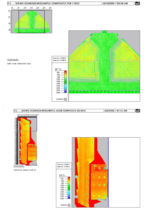
ACQUISITION / ANALYSIS
The system is supplied with the latest SDI-WinScan multi-tasking acquisition and analysis package designed for high throughput production applications. A technical description of the features and benefits of this high performance industrial package is attached. Some of the key features are:
Another time saving feature of the fully integrated motion control and data acquisition package is the ability to perform mini-scans. Areas of interest can be tagged on the data file and the system will automatically drive back to them and re-scan the area using selected defect evaluation scan parameters such as full waveform capture.
INSTALLATION
The system will be fully assembled and made operational at the SDI facility in Camarillo for customer buy off. The Acceptance Test Procedure (ATP) will be carried out using the test samples supplied by the customer. SDI will address any items requiring rectification prior to authorization for shipment by the customer representative. Upon receiving approval, SDI will dismantle, crate and ship the system. SDI will carry out site preparation prior to the arrival of the system. The system will then be assembled and made operational on site. The ATP will then be repeated. The system timeline is attached.
TRAINING
SDI provide a comprehensive training program including 5 days training of personnel in the operation and routine maintenance of this equipment. This training will take place either at the SDI facility or at the customer site after installation.
![]()