SDI-5750 Independent Tower Through Transmission 3D Scanning Ultrasonic System
![]()
- System Overview
- Mechanical Configuration
- Electrical Configuration
- Instrumentation / Motion Control
- Acquisition/Analysis
- Installation/Training
SDI-5750 SYSTEM OVERVIEW
 The SDI-5750 is a full feature high performance 3D curve scanning UT system designed for incorporation into airframe Lean Manufacturing environments. It incorporates all the features of a large scale fixed gantry system such as the SDI-5410, into a relocatable unit.
The system is designed to inspect a complete range of part geometries, such as aircraft control surfaces, wings, doors etc in addition to highly contoured fuselage and cabin components.
The motion control, data acquisition and instrumentation components can be installed in a system control room, or operated from a shop floor console. The system is based on modules widely used in SDI’s product range.
All components/modules used in the system are designed and manufactured in-house by SDI in their Camarillo, California facility.
Note: This specification is for a typical SDI-5750 Inspection System and is for information only. The details may differ significantly from those proposed for specific customer requirements.
The specification provided in the Statement of Compliance and formal quotation supersedes this document.
SDI-5750 SYSTEM FEATURES:
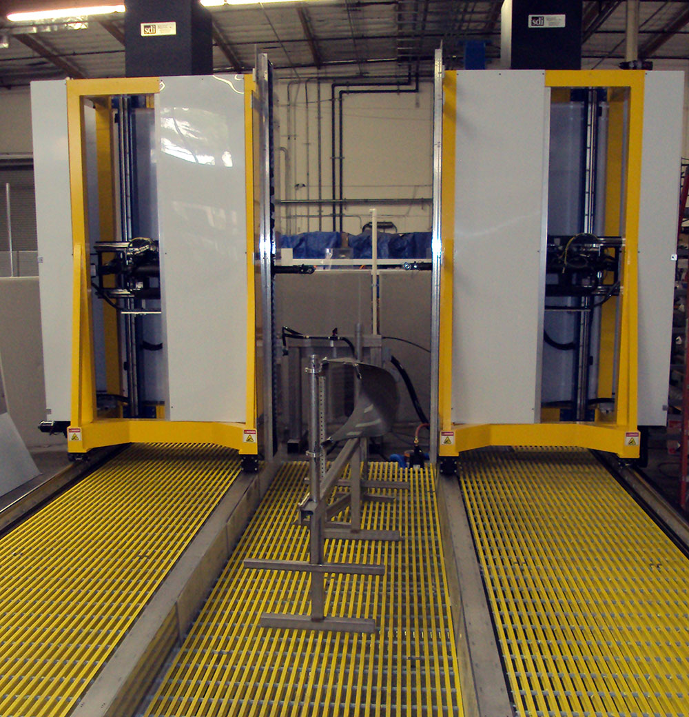
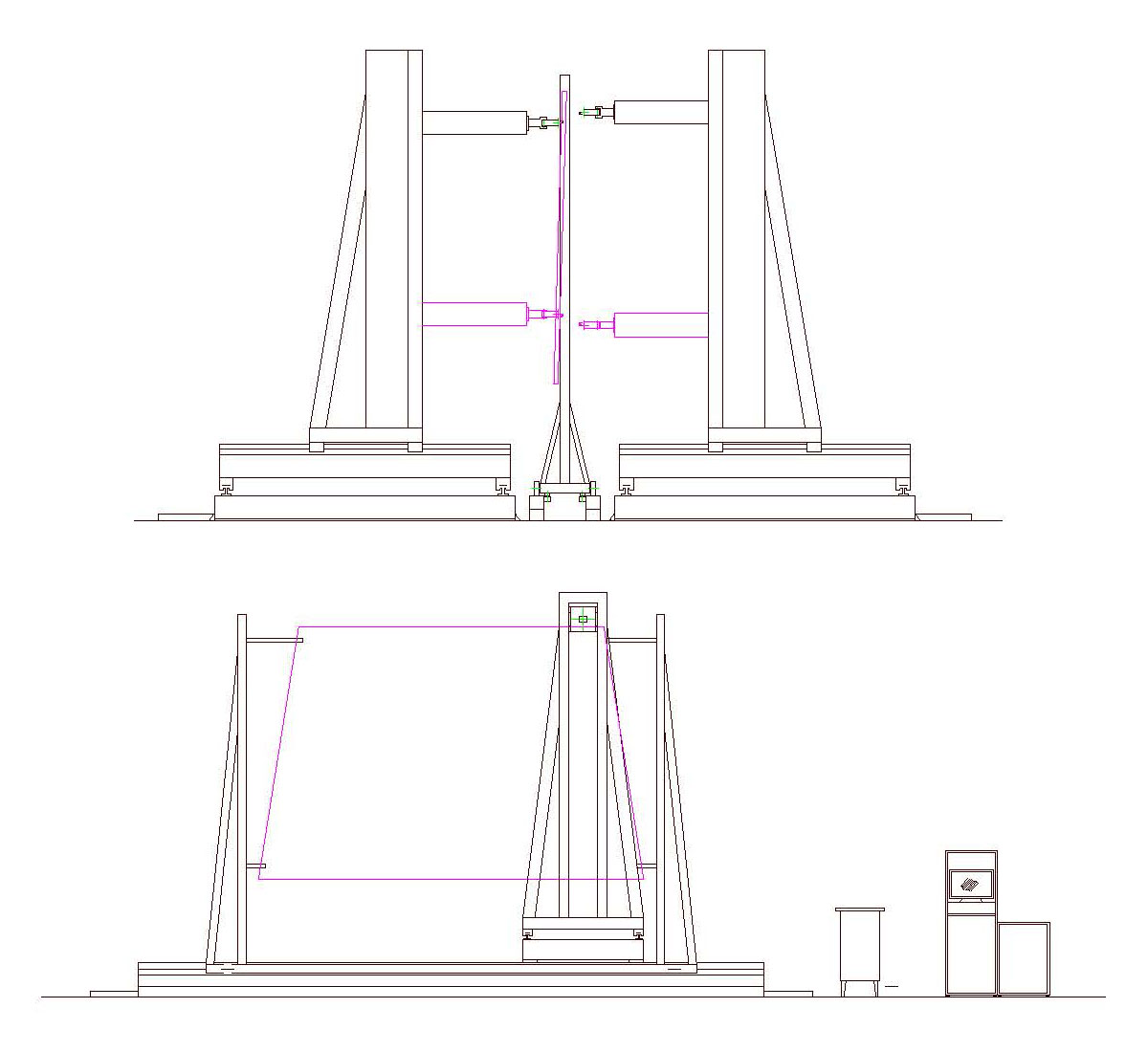
MECHANICAL CONFIGURATION
The system is turnkey, stand alone and fully self-contained. The mechanical configuration is outlined in the attached concept drawing. All support frame members are welded box section.
The frame is mounted on a rigid platform fitted with water containment and recirculation components. The Y axis arms are designed to accept a range of interchangeable gimbal assemblies for various applications. The standard extended reach gimbal/gimbal unit is used for the majority of applications where access is not a problem.
Where there are restrictions, the compact gimbal/swivel unit is more appropriate. The axes of motion provided on the system are shown in the table below:
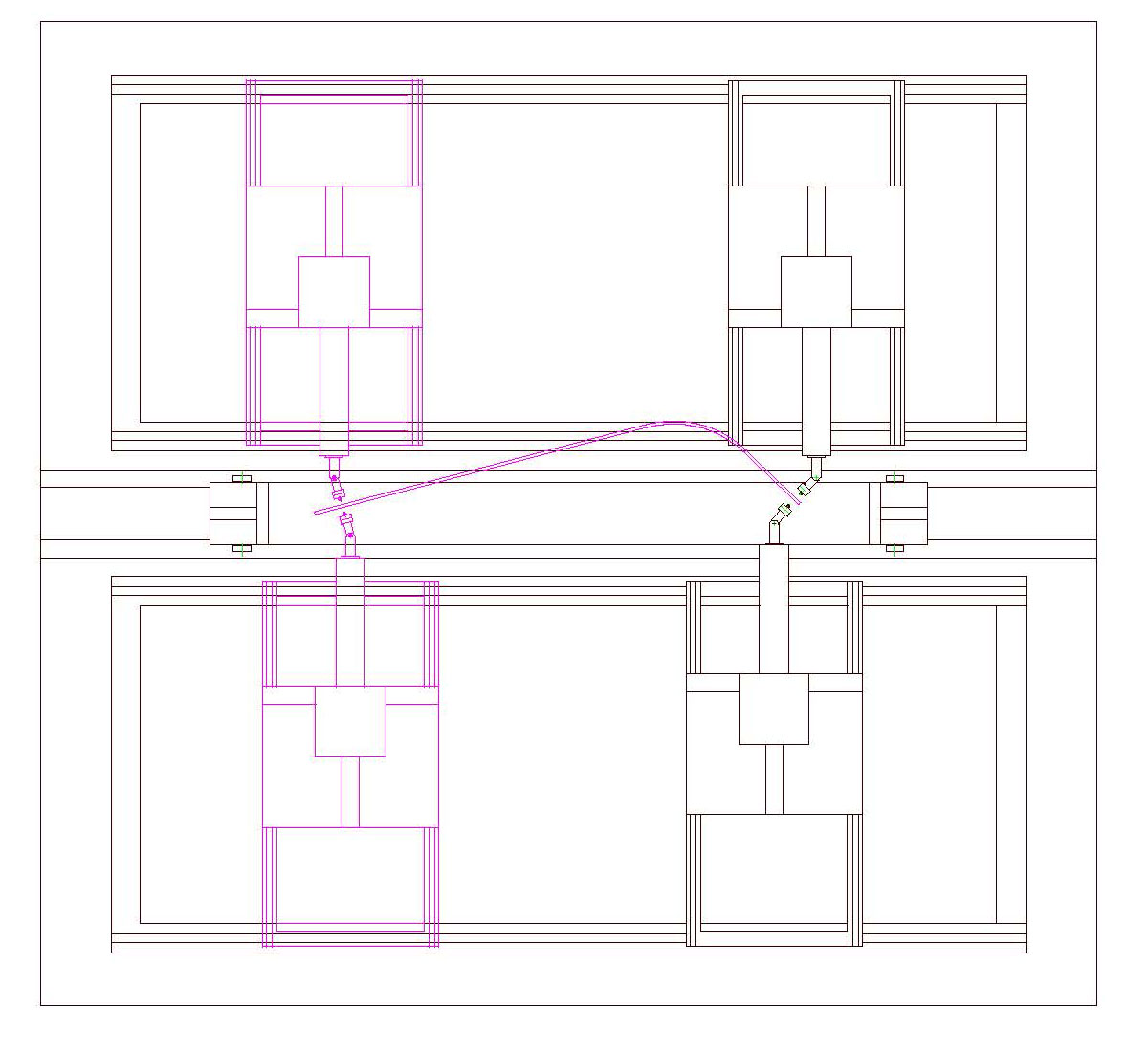
The axes of motion provided on the system are shown in the table below: Typical ranges are given. These will vary according to customer requirements.
| Axis | Description | Range | Speed | Resolution | Accuracy |
|---|---|---|---|---|---|
| X | Primary axis along the frame. d.c. servo drives. | 24 ft. | 24 in/sec | .001 in. | .004 in/ft |
| Z1, Z2 | Vertical column rack and pinion drives. d.c. servo drives. | 120 in. | 15 in/sec | .001 in. | .004 in/ft |
| Y1, Y2 | Lateral arms. Rack and pinion drive with d.c. motors and resolvers. | 68 in. | 12 in/sec | .001 in. | .004 in/ft |
| A1, A2 | Gimbal in Y, Z plane | +/- 90 deg | 30 deg/sec | .01deg | 0.01deg |
| B1, B2 | Gimbal in Y, Z plane | +/- 90 deg | 30 deg/sec | .01deg | 0.01deg |
LINEAR DRIVES
For all linear ways, heavy duty helical rack and pinion drive provides precise positioning and encoder feedback. The independent tower design also simplifies maintenance and repair as the drive components for all axes are accessible from ground level.
The linear ways for Z are precision stainless steel, heavy duty, V rails. These are also fitted with precision rack and pinion drives. The Z axis carriages are counter balanced with safety braking . All drives are closed loop d.c. with encoders/resolvers.
GIMBAL DRIVES
The gimbals are harmonic drive d.c. servos with integral high precision resolvers. The units are housed in oil filled stainless steel enclosures. The squirter is attached to the gimbals by a magnetic mount.
CONTROL CONSOLE
The mobile control console can be positioned anywhere within reasonable distance from the system. Current SDI systems have similar remote consoles up to 80 ft. from the scanner.
It is fitted with two 19 inch monitors linked in the Windows operating environment to allow windows to be dragged from one screen to the next, or expanded over two screen.
The console requires a single 110V 60 Amp single phase supply. SDI will install the necessary transformers to achieve this from the customer’s supply.
The console houses all the computing, drive and instrumentation components required to operate the system. The enclosure includes a filtration and refrigeration unit.
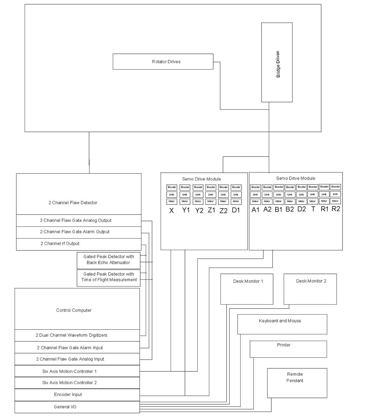
ELECTRICAL CONFIGURATION
The electrical configuration describes the components and interconnections for the motion control, drive, instrumentation and data acquisition sub systems. The majority of the components are housed in the system console. All system components meet applicable US and International safety codes.
Apart from the very low current ultrasonic signals, no voltages greater than 70 volts are present anywhere on the system outside the control console. The electrical layout is shown below:
INSTRUMENTATION
The system can be supplied with any third party systems instrument such as the Krautkramer USPC2100-2, two channel unit. When installed with the SDI sequencer unit, the system can be configured to be able to provide simultaneous pulse echo from each side together with two through transmission tests, resulting in the acquisition of four channels of data in a single scan. A range of auxiliary instrumentation can be provided to aid in the inspection of the more complex highly attentive lay-ups. This will include log amplifiers, pre-amplifiers, and tone burst pulsers.
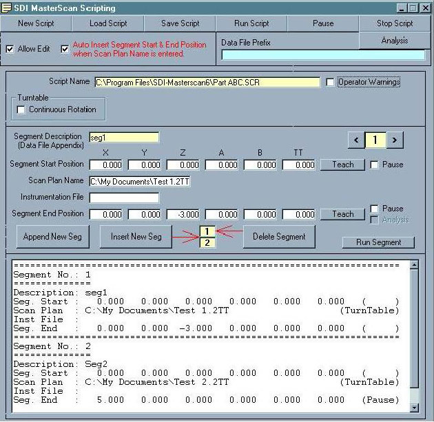
MOTION CONTROL
The motion control is provided by the SDI-1830 MasterScan advanced controller. Designed specifically for ultrasonic applications, it features ultrasonic functional axes and scripted scan plans. This means that complex motion control and acquisition activities unique to ultrasonic inspection techniques are available to the operator through simple commands using ultrasonic terminology. The operator can construct complex scans by chaining together individual motion commands, scan plans and instrument set-ups. Full details of MasterScan are given in the data sheet. Some of the key features are:
- Functional axes using standard UT terminology
- Import/Export of scan plans to CAD programs
- Automated normalization
- Auto teach of scan plans
- Integrated instrument control coordinated with the motion along a
- scan trajectory
- Scripted scan plans
- Chained scans
- Dual independent search tubes performing different scans
- simultaneously
- Stop on defect
- Return to defect
- Display of scan progress and time to finish
- Variable turntable rotation to maintain constant surface speed with changing diameter
ACQUISITION / ANALYSIS
The system is supplied with the latest SDI-WinScan multi-tasking acquisition and analysis package designed for high throughput production applications. A technical description of the features and benefits of this high performance industrial package is attached. Some of the key features are:
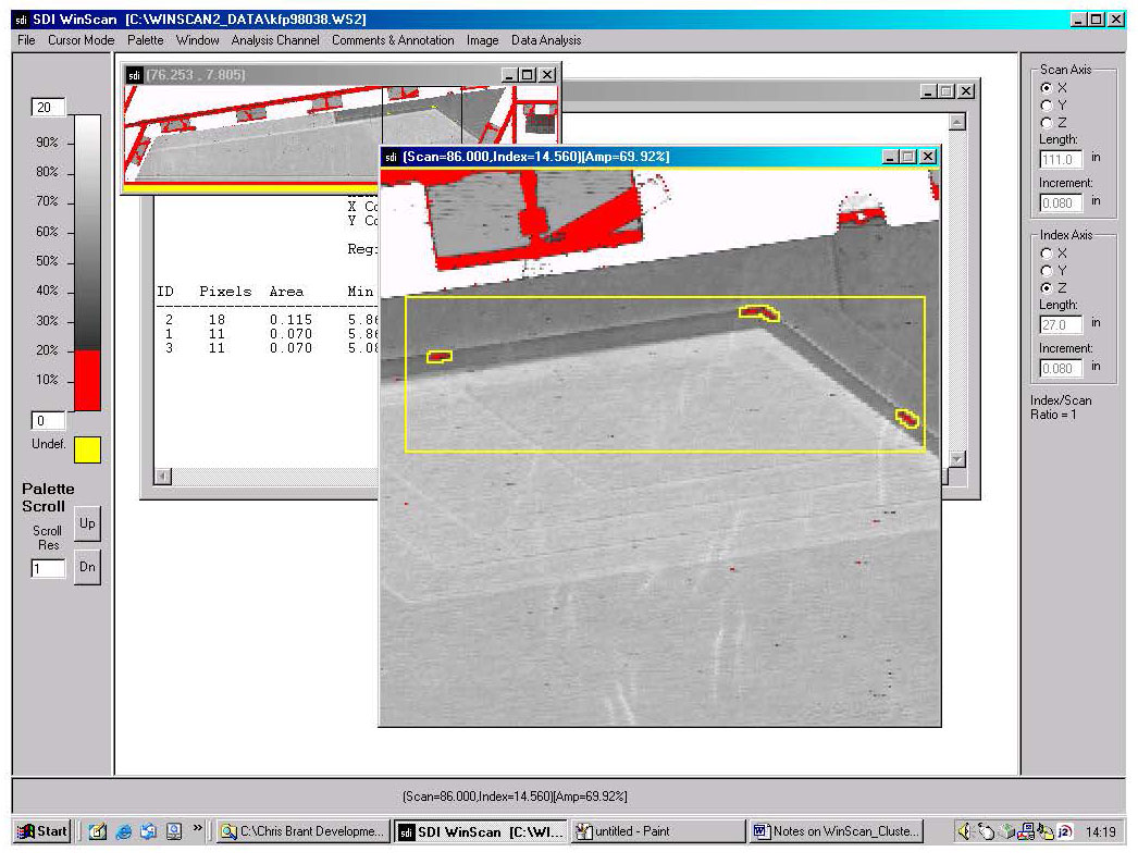
Another time saving feature of the fully integrated motion control and data acquisition package is the ability to perform mini-scans. Areas of interest can be tagged on the data file and the system will automatically drive back to them and re-scan the area using selected defect evaluation scan parameters such as full waveform capture. 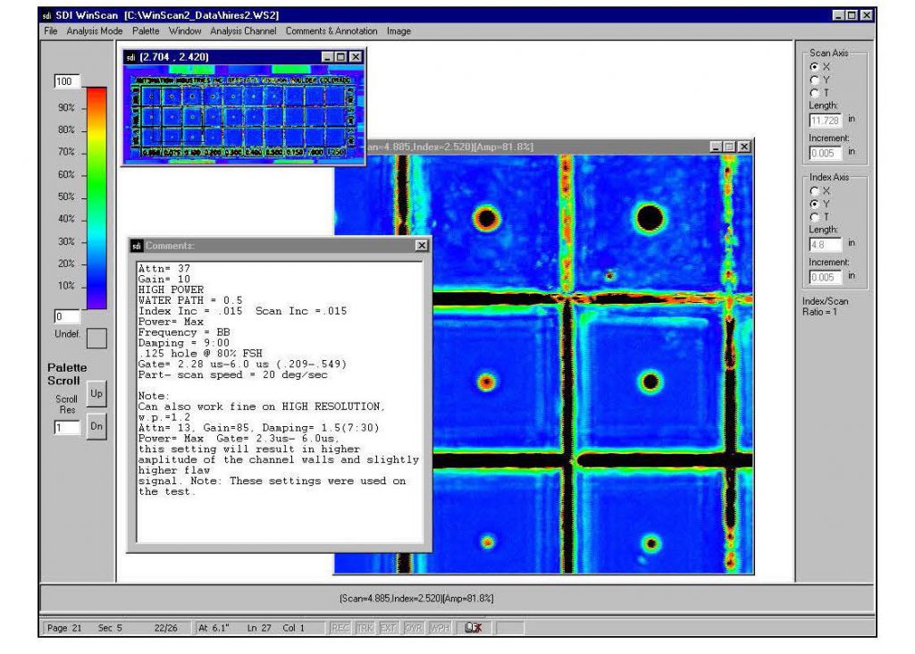
INSTALLATION
The system will be fully assembled and made operational at the SDI facility in Camarillo for customer buy off. The Acceptance Test Procedure (ATP) will be carried out using the test samples supplied by the customer. SDI will address any items requiring rectification prior to authorization for shipment by the customer representative. Upon receiving approval, SDI will dismantle, crate and ship the system. SDI will carry out site preparation prior to the arrival of the system. The system will then be assembled and made operational on site. The ATP will then be repeated. The system timeline is attached.
TRAINING
SDI provide a comprehensive training program including 5 days training of personnel in the operation and routine maintenance of this equipment. This training will take place either at the SDI facility or at the customer site after installation.
![]()