SDI-5810 Turntable Through Transmission Ultrasonic System
![]()
- System Overview
- Mechanical Configuration
- Electrical Configuration
- Instrumentation / Motion Control
- Acquisition/Analysis
- Installation/Training
SDI-5810 SYSTEM OVERVIEW
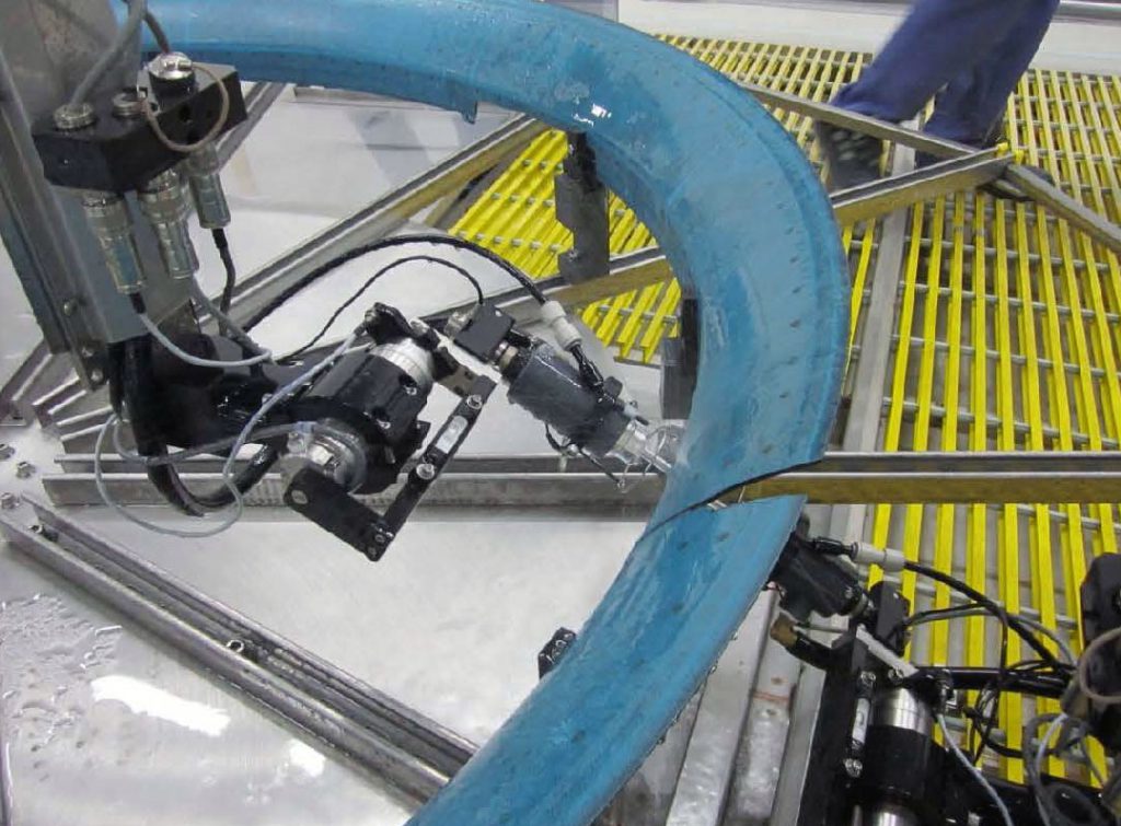
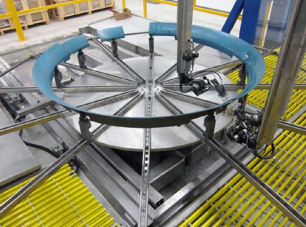
The SDI-5810 is a seven axis high performance UT static gantry system designed for the inspection of large circular airframe components such as engine nacelles.
The seven axis design (Y1, Y2, Z1, Z2, B1, B2, T), provides a lower cost system for components which have curvature in the YZ plane only.
For full 3D scanning the SDI 5420, 5680 and 5700 series systems are available. A turntable is fully integrated into the programmable motion sequence.
The motion control, data acquisition and instrumentation components can be installed in a system control room, or operated from a shop floor console.
The system can be operated in English or Metric units simplifying inspection of components from a variety of sources. The system can be enhanced for parts which are not circular by extending the gantry and adding X axis motion.
The system is based on modules widely used in SDI’s product range. All components/modules used in the system are designed and manufactured in-house by SDI in their Camarillo, California facility.
MECHANICAL CONFIGURATION
The system is turnkey, stand alone and fully self-contained. The mechanical configuration is outlined in the attached concept drawing.
The gantry is fabricated from heavy section steel box section coated with an epoxy finish designed for use in adverse environments. The bridge frame is fixed in the X direction with Y, Z and B motion provided on two search tubes to allow following of contoured volumes of revolution on the turntable.
A sump is provided with water containment and recirculation components. The system can be mounted above ground. It is necessary to anchor the system to the ground for additional rigidity.
BRIDGE Y AXIS
The bridge is fabricated from heavy aluminum box section with a rigid box girder construction. Mounted to it are the precision ball shafts for the Y-axis carriages which support the Z-axis vertical drive housings. The design incorporates methods of adjusting the orthogonality and alignment of the Y and Z axes.
GIMBALS
The gimbals incorporate d.c. drives with resolvers and zero backlash gearboxes. The units are housed in air purged stainless steel enclosures. The squirter is attached to the gimbals by a magnetic mount.
| Axis | Description | Range | Speed | Resolution | Repeat-ability | Accuracy |
|---|---|---|---|---|---|---|
| T | Turn Table belt drive. | 360 degrees | 10 rpm | 0.05 degrees | 0.05 degrees | 0.1 degrees |
| Y1, Y2 | Belt drive with brushless d.c. motors and resolvers. | 6 ft. | 16 ips | 0.001 in. | 0.002 in. | +/-0.010 in. |
| Z1, Z2 | Vertical column rack and pinion drives. d.c. servo drives with resolver. | 6 ft. | 6 ips | 0.001 in. | 0.002 in. | +/-0.010 in. |
| B1, B2 | Gimbal in Y, Z plane | +/- 90 deg | 30 deg/sec | .01deg | .01deg | 0.01deg |
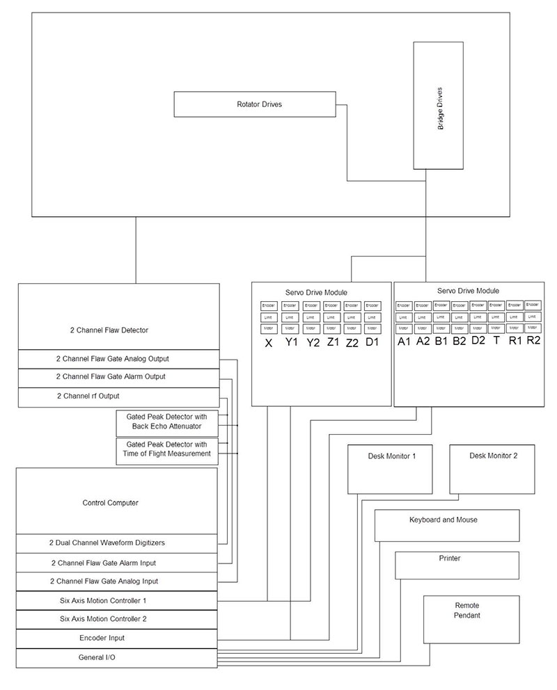
ELECTRICAL CONFIGURATION / CONTROL CONSOLE
The mobile control console can be positioned anywhere within reasonable distance from the system. Current SDI systems have similar remote consoles up to 80 ft. from the scanner.
It is fitted with two 21 inch monitors linked in the Windows operating environment to allow windows to be dragged from one screen to the next, or expanded over two screens. The console requires a single 110V 60 Amp single phase supply.
The console houses all the computing, drive and instrumentation components required to operate the system. The enclosure includes a filtration and refrigeration unit.
The electrical configuration describes the components and interconnections for the motion control, drive, instrumentation and data acquisition sub systems. The majority of the components are housed in the system console.
All system components meet applicable US and International safety codes.Apart from the very low current ultrasonic signals, no voltages greater than 70 volts are present anywhere on the system outside the control console.
A typical electrical layout is shown below. The layout of a particular system will depend upon the configuration and features of the instrumentation ordered.
The electrical layout is shown below:
INSTRUMENTATION
Typical systems are supplied with the Socomate USPC 3100–2, two channel systems instrument. This is a modular, multi-channel flaw detector comprising pulser, receiver, flaw gate and optional thickness modules.
The unit will be configured to be able to provide simultaneous pulse echo from each side together with two through transmission tests, resulting in the acquisition of four channels of data in a single scan.
A range of auxiliary instrumentation will be provided to aid in the inspection of the more complex highly attenuative lay-ups. This will include a log amplifier, pre-amplifier, and tone burst pulser.
MOTION CONTROL
Motion control is provided by the widely used SDI-MasterScan program. A technical specification is attached.
ACQUISITION / ANALYSIS
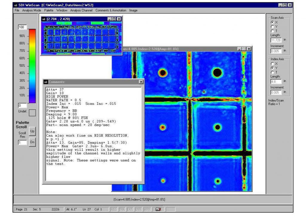
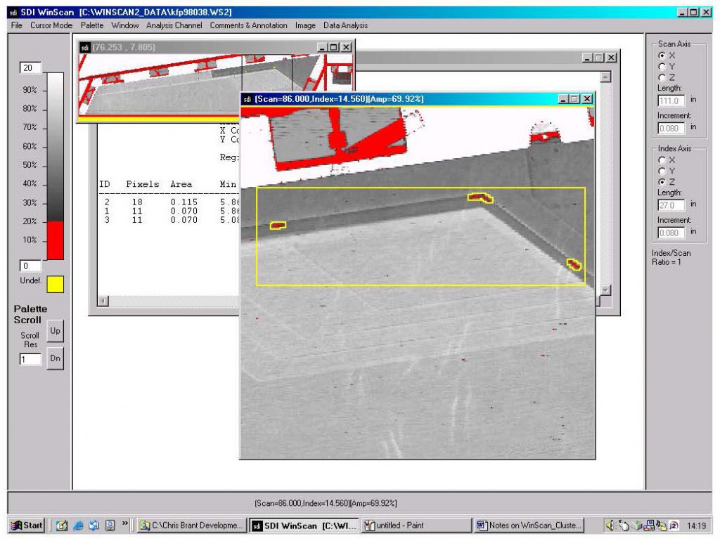
The system is supplied with the latest SDI-WinScan multi-tasking acquisition and analysis package designed for high throughput production applications. A technical description of the features and benefits of this high performance industrial package is attached. Some of the key features are:
Another time saving feature of the fully integrated motion control and data acquisition package is the ability to perform mini-scans. Areas of interest can be tagged on the data file and the system will automatically drive back to them and re-scan the area using selected defect evaluation scan parameters such as full waveform capture.
INSTALLATION
The system will be fully assembled and made operational at the SDI facility in Camarillo for customer buy off. The Acceptance Test Procedure (ATP) will be carried out using the test samples supplied by the customer. SDI will address any items requiring rectification prior to authorization for shipment by the customer representative. Upon receiving approval, SDI will dismantle, crate and ship the system. SDI will carry out site preparation prior to the arrival of the system. The system will then be assembled and made operational on site. The ATP will then be repeated. The system timeline is attached.
TRAINING
SDI provide a comprehensive training program including 5 days training of personnel in the operation and routine maintenance of this equipment. This training will take place either at the SDI facility or at the customer site after installation.
![]()