SDI-5230 Automated Ultrasonic Bar Inspection System
![]()
- System Overview
- Mechanical Configuration
- Electrical Configuration
- Instrumentation / Motion Control
- Acquisition/Analysis
- Installation/Training
SDI-5230 SYSTEM OVERVIEW
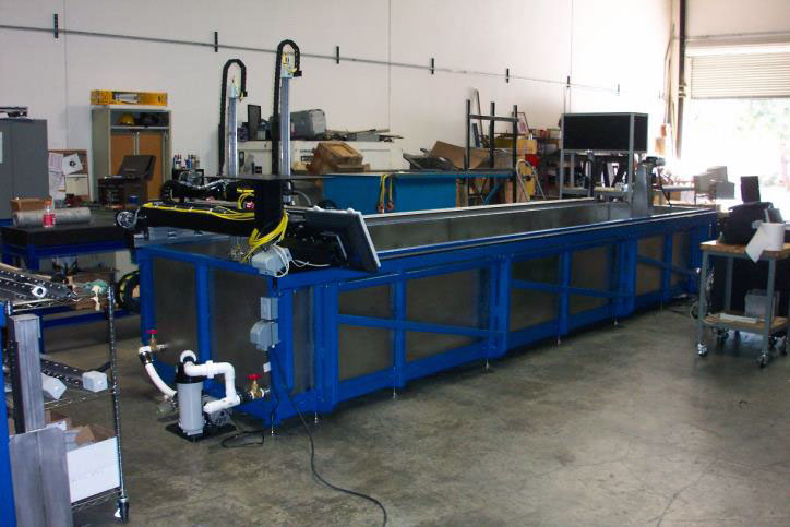
This specification is for an advanced rotator system for the inspection of aero engine components. The equipment components include a heavy duty precision bridge mounted on a stainless steel immersion tank fitted with one of the SDI-1330 series rotators.
The precision search tube is configured to accept a range of gimbal options. The equipment will operate with any system level ultrasonic instrumentation. It is designed to achieve the accuracy and resolution required at high throughput speeds in a harsh operating environment.
 SDI have supplied systems of this type for testing product from all major aero engine and rocket motor producers.
In addition to being approved by all major aero-engine manufacturers, the following advanced features of SDI systems give major advantage over competitor’s equipment in terms of ease of use and inspection set-up and test time;
The service, maintenance and technical support facilities offered by SDI can be tailored to meet a wide range of customer requirements. Customers who purchase our equipment receive the complete range of services free of charge for the first year following equipment installation.
Although the SDI 5230 will operate with most system flaw detectors, incorporating one of the SDI USPC-7100 high performance systems instruments gives the following additional benefits.
MECHANICAL CONFIGURATION
 The system consists of floor mounted heavy gauge stainless steel tank with a re-enforced base suitable for supporting rotators up to 35ft (10m) long. A variety of transducer holders and bar followers is available.
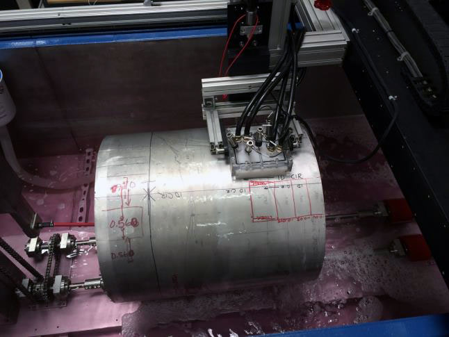
These range from a single channel dual axis motorized gimbal to a multi-channel bar follower where the transducers are mounted in-line in a housing which rides in contact with the bar. The bar to be tested is loaded onto the rollers and the transducer/follower assembly positioned above it.
As the bar is rotated, the transducer assembly traverses the entire length of the bar. All test parameters, including rotator speed, helix pitch etc are controlled by the SDI-1830-UTB system controller. The time to test a bar is dependent on the test standard defect size and the bar diameter.
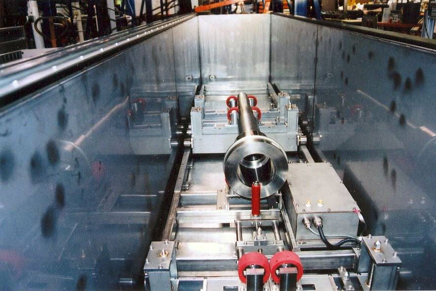
 The 1335 and 1336 series rotators consist of separate drive and idler units providing, in most cases, two point support for the bar under test. This provides greater tolerance to slightly bent bars than the multiple roller designs.
The drives are installed in oil filled underwater housings. Both the drive and idler stations can be relocated to any point along tracks mounted to the support frame.
Adjustable height idler stations allow the inspection of cylindrical parts with multiple varying diameters. The modular design allows rapid reconfiguration of the system to accommodate different lengths and diameters of bar.
The lower cost 1334 bar rotator type is a standard multi roller configuration mounted on two parallel shafts. The roller spacing can be adjusted to accommodate different bar diameters. The drive is mounted on an above water extension.
GANTRY-X AXIS
The gantry is fabricated from heavy steel box section with a high redundancy outrigger design calculated to provide the required rigidity and stability for the large accelerating mass of the bridge and search tubes. The gantry is fitted with ground tracks with leveling jack screws and guide bars.
Mounted to the tracks are the linear ways and heavy duty rack and pinion drive components to provide precise positioning and encoder feedback. The gantry also carries the cable distribution components. All drives are closed loop d.c. servos with encoders/resolvers.
BRIDGE Y AXIS
The bridge is fabricated from heavy aluminum box section with a rigid box girder construction. Mounted to it are the precision V ways for the Y-axis carriages which support the Z-axis vertical drive housings. The design incorporates methods of adjusting the orthogonality and alignment of the X, Y and Z axes.
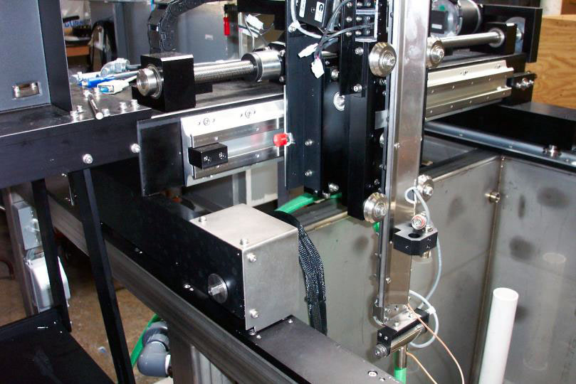
SEARCH TUBES Z-AXIS
The search tubes incorporate several novel design features to provide the required adjustments and accuracy to maintain the alignment of two independent search tubes during high speed 3D contour following. The stainless steel cruciform construction, precision rack and pinion drive and V ways provide single search tube systems with these benefits even though the alignment requirement does not exist.
GIMBALS
The gimbals are closed loop servos with integral high precision resolvers. The units are housed in oil filled stainless steel enclosures. The transducer is attached to the gimbals by a UHF mount.
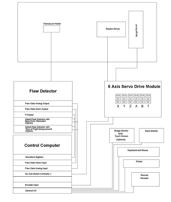
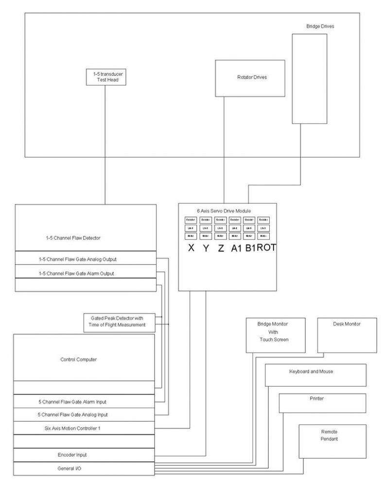
ELECTRICAL CONFIGURATION
The electrical configuration describes the components and interconnections for the motion control, drive, instrumentation and data acquisition sub systems. The majority of the components are housed in the system console. All system components meet applicable US and International safety codes. Apart from the very low current ultrasonic signals, no voltages greater than 70 volts are present anywhere on the system outside the control console.
CONTROL CONSOLE
The mobile control console can be positioned anywhere within reasonable distance from the system. Current SDI systems have similar remote consoles up to 80 ft. from the scanner.
The system can be configured with two 19 inch LCD monitors linked in the Windows operating environment to allow windows to be dragged from one screen to the next, or expanded over two screens. The console requires a single 110V 60 Amp single phase supply.
SDI will install the necessary transformers to achieve this from the customer’s supply. The console houses all the computing, drive and instrumentation components required to operate the system.
The enclosure includes a filtration and refrigeration unit where required. The electrical layout is shown below:
INSTRUMENTATION
All SDI systems are able to operate with a variety of flaw detectors. Systems have been installed using instruments supplied by all major instrument manufacturers. Incorporating one of the SDI USPC-7100 high performance systems instruments gives the following additional benefits:
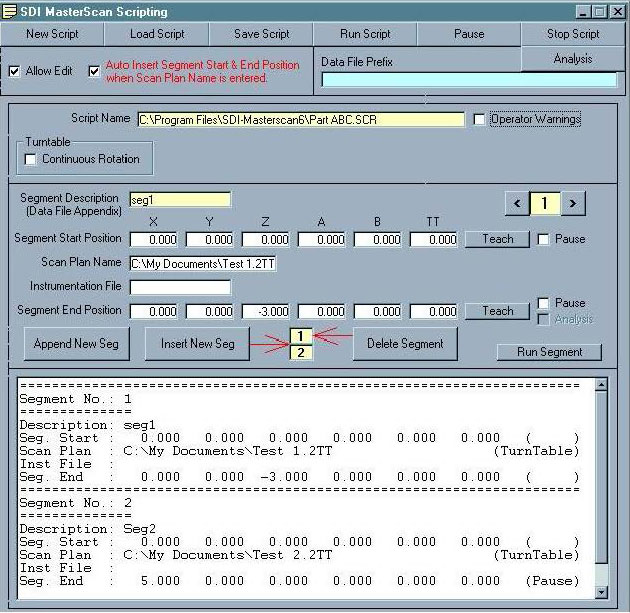
MOTION CONTROL
The motion control is provided by the SDI-1830 MasterScan advanced controller. Designed specifically for ultrasonic applications, it features ultrasonic functional axes and scripted scan plans. This means that complex motion control and acquisition activities unique to ultrasonic inspection techniques are available to the operator through simple commands using ultrasonic terminology. The operator can construct complex scans by chaining together individual motion commands, scan plans and instrument set-ups. Full details of MasterScan are given in the data sheet. Some of the key features are:
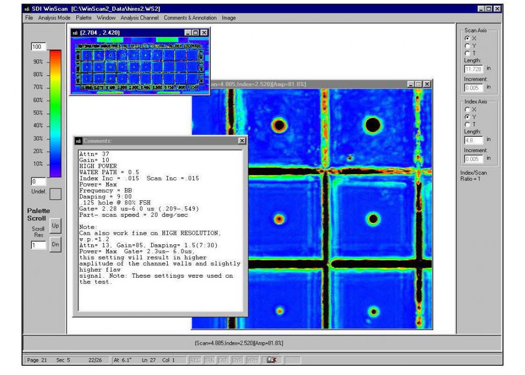
ACQUISITION / ANALYSIS
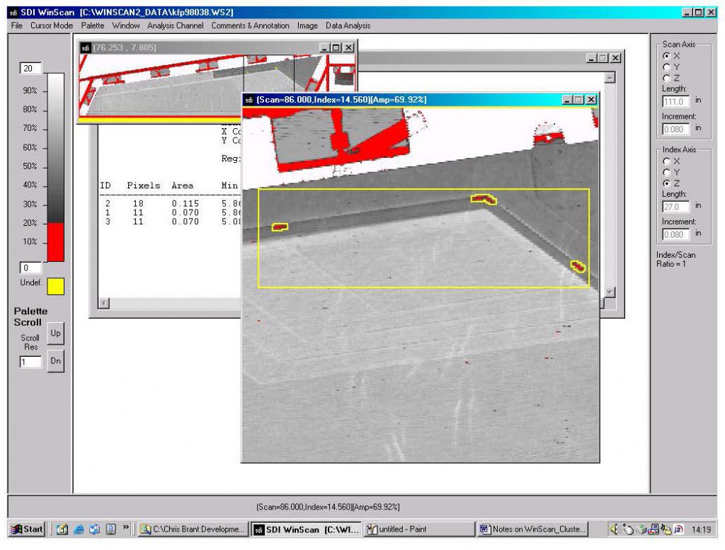
The system is supplied with the latest SDI-WinScan multi-tasking acquisition and analysis package designed for high throughput production applications. A technical description of the features and benefits of this high performance industrial package is attached. Some of the key features are:
Another time saving feature of the fully integrated motion control and data acquisition package is the ability to perform mini-scans. Areas of interest can be tagged on the data file and the system will automatically drive back to them and re-scan the area using selected defect evaluation scan parameters such as full waveform capture.
INSTALLATION
The system will be fully assembled and made operational at the SDI facility in Camarillo for customer buy off. The Acceptance Test Procedure (ATP) will be carried out using the test samples supplied by the customer. SDI will address any items requiring rectification prior to authorization for shipment by the customer representative. Upon receiving approval, SDI will dismantle, crate and ship the system. SDI will carry out site preparation prior to the arrival of the system. The system will then be assembled and made operational on site. The ATP will then be repeated. The system timeline is attached.
TRAINING
SDI provide a comprehensive training program including 5 days training of personnel in the operation and routine maintenance of this equipment. This training will take place either at the SDI facility or at the customer site after installation.
![]()